Contents
Introduction to ElectronicsConductors, Insulators and Semi-conductors
Electricity, Voltage, Current and Resistance
Power
Ohm's Law
Electric Circuit
Components of a Circuit
LED
Resistor
Capacitor
Switches
Relay
Diode
Transistor
Integrated Circuit
Measuring Electrical Parameters
Soldering
Electronics:A first Course
Introduction to Electronics
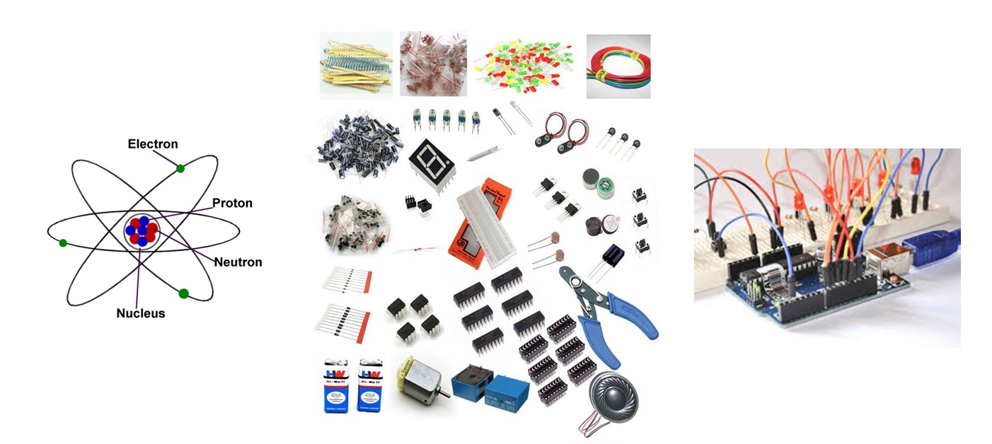
In this fast developing society, electronics has come to stay as the most important branch of engineering. Electronic devices are commonly used in a large number of applications that formerly relied on mechanical or electric systems for their operation. Examples are electronic controls in automatic cameras, electronic ignition systems in cars, and electronic control in domestic equipment, such as washing machines.
The branch of engineering which deals with current conduction through a vacuum or gas or semiconductor is known as electronics.Electronics essentially deals with electronic devices and their utilization. It handles electric circuits containing passive elements (Resistors, Capacitors etc..), active elements (Diodes, Transistors, LEDs etc..), and other underlying techniques making it as an important part of engineering.
Role of Electronics:
Electronics has an all-important role in a country's development process today. Electronics plays a catalytic role in enhancing production and productivity in key sectors of the economy, whether it relates to infrastructure, process industries, communication, or even manpower training. High-tech areas today depend heavily on electronics.
Electronics is conventionally classified into consumer, industrial, defence, communications and information processing sectors. In recent times, medical electronics, and systems for transportation and power utilities have become important segments on their own.
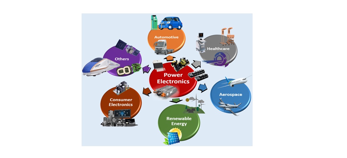
Applications of Electronics:
Electronics is widely used in Consumer Electronics, Automotive, telecommunication, Healthcare, Aerospace and Robotics.
Matter to Electrons
Matter:
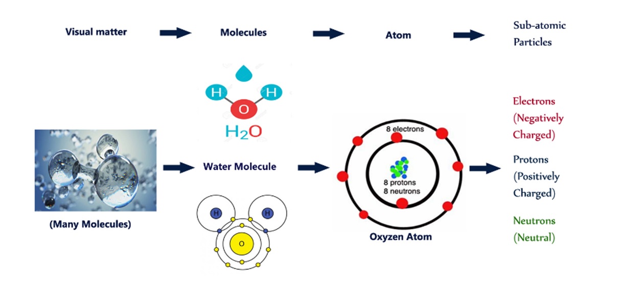
Everything in the world is made of matter. Matter is anything that has mass (weight) and occupies space. Matter can be made up of a group or series of different atoms to form a molecule. Matter has three states: Solid, Liquid, and Vapor.
Molecule:
All matter is made of molecules, or combinations of atoms, that are bound together to produce a given substance, such as water or salt or glass. If you could keep dividing water, for example, into smaller and smaller drops, you would eventually arrive at the smallest particle that was still water. That particle is a molecule, which is defined as the smallest bit of a substance that retains the characteristics of that sub-stance.
The molecule of water is known in chemical notation as H2O. That means the molecule is actually made up of two atoms of the element hydrogen (H) and one atom of the element oxygen (O). These atoms, themselves, are not water but the separate elements of which the molecule of water is composed.
Molecules are made up of atoms, which are bound together to produce a given substance.
Atom:
One of the basic building blocks in the universe for matter is the atom. All matter - gas, liquid, or solid - is made up of molecules or atoms joined together. These atoms are the smallest particle into which an element or substance can be divided without losing its property.
Atomic Particles:
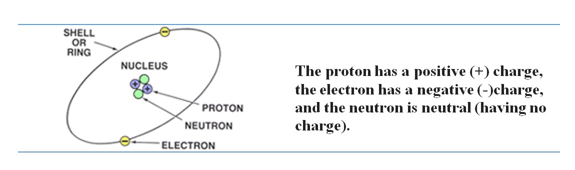
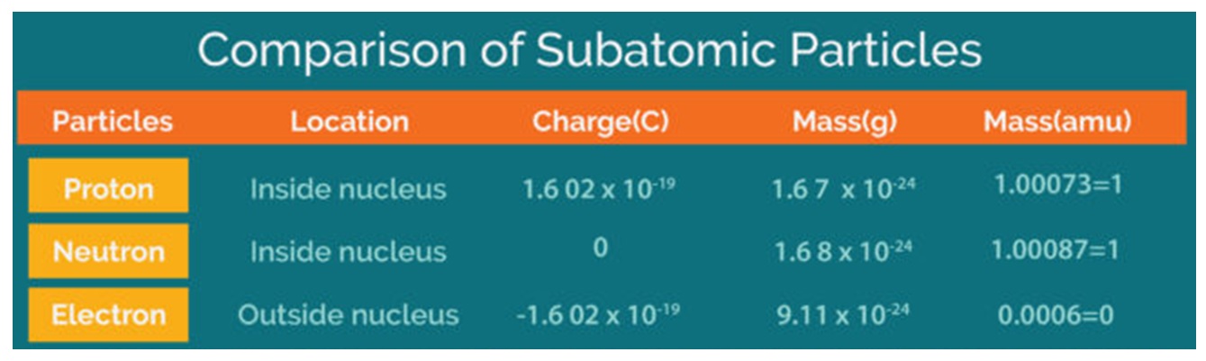
Atoms are made of even smaller particles, called protons, neutrons, and electrons. These particles differ in weight (the proton is much heavier than the electron) and charge. The weights of the particles need not concern you, but the charge is extremely important in electricity. The proton has a positive (+) charge, the electron has a negative (-)charge, and the neutron is neutral.
Protons and neutrons form an atom's nucleus (its center), and electrons orbit the nucleus like planets orbiting the sun. The electrons move around the nucleus of the atom in various orbits. Such electrons are not free: They are locked into the atom because they are attracted by the nucleus.
Balanced Atom:
Atoms normally have an equal number of electrons and protons. Atoms have no electrical charge. They are neither positive nor negative. They are electrically neutral or BALANCED. The negative charge of the electrons will cancel the positive charge of the protons, thus balancing the charge of the atom. This cancellation of charges creates a natural attraction or bonding between the positive proton and the negative electron.
In a stable or balanced atom the orbiting electrons remain in their orbits as long as nothing upsets the balance.When something upsets this balance, then some of the electrons become "knocked" out of their orbits.
This unbalanced condition can be caused by rubbing cat's fur on amber, passing a wire through a magnetic field, or putting two chemicals together, as in a dry cell battery.
Ion Particles:
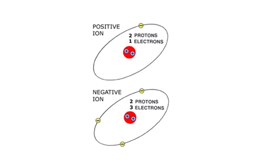
When an atom loses or gains an electron, an imbalance occurs. The atom becomes either a positively or negatively charged particle called an ION.These unbalanced charged ION particles are responsible for electron flow (electricity). IONs will take or release an electron to become balanced again.
A positive (+) ION has one less electron than it has protons. A negative (-) ION has one more electron than it has protons. The positive ION attracts a negative ION to become balanced. This attraction or difference in electrical potential causes electron flow.
Electron Orbits:
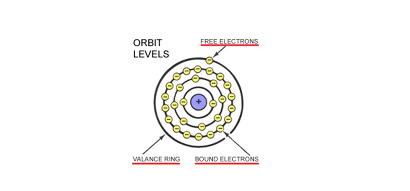
Electrons rotate around the atom at different orbits called Rings, Orbits, or Shells. BOUND ELECTRONS orbit the nucleus on the inner rings. Bound electrons have a strong magnetic attraction to the nucleus. FREE ELECTRONS orbit on the outermost ring which is known as the VALANCE RING.
Free Electrons:
Only the FREE ELECTRONS in the outermost shell (Valance Ring) are free to move from atom to atom. This movement is called ELECTRON FLOW. These FREE ELECTRONS are loosely held and can easily be moved to another atom or ion. Because of their distance from the nucleus, free electrons have a weak magnetic attraction. Since this attraction is not as strong to the nucleus as the bound electrons on the inner orbits, the free electrons move easily from atom to atom.
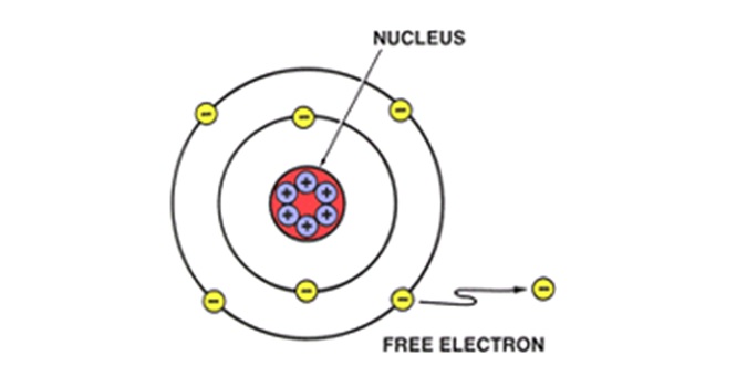
Free electrons are produced when some force disturbs the stable relationship of electrons and protons in an atom. This force, which "knocks" electrons out of orbit, can be produced in a number of ways, such as: by moving a conductor through a magnetic field; by friction, as when a glass rod is rubbed with silk; or by chemical action, as in a battery. The force "frees" the electrons from their atoms; these electrons are called free electrons. When an electric force is applied to a material such as copper wire, electrons in the outer orbits of the copper atoms are forced out of orbit and impelled along the wire.
The electrons that have been forced out of orbit are called free electrons. Electric Current depends on the movement of free electrons.
Electric Current:
The movement of free electrons along a wire is what we call electric current. it cannot exist where there are no free electrons.
Electrostatic Force:
Electrostatic force (also called Coulomb's law) is a force that operates between charges. It states that charges of the same type repel each other, while charges of opposite types are attracted together. Opposites attract, and likes repel.
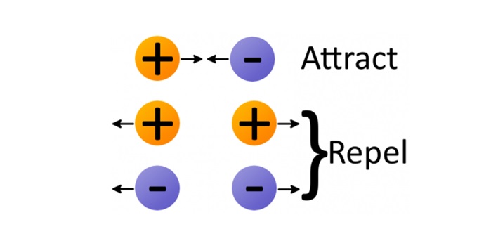
The amount of force acting on two charges depends on how far they are from each other. The closer two charges get, the greater the force (either pushing together, or pulling away) becomes.
Thanks to electrostatic force, electrons will push away other electrons and be attracted to protons. This force is part of the "glue" that holds atoms together, but it's also the tool we need to make electrons (and charges) flow!
Back to contents
Conductors, Insulators and Semi-conductors
Electric current moves easily through some materials but with greater difficulty through others. Let us see how the action of free electrons is related to current flow through these materials.
Conductors:
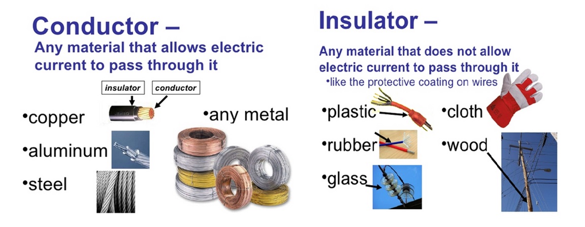
Some substances let electric charge flow through them. These substances are called conductors. Conductors permit the movement of a large number of free electrons. One of the best-known conductors is copper. It conducts so well because the electrons of copper atoms are able to escape easily from the atoms. The best conductors are metals. Copper is the most commonly used conductor because it conducts electric charge better than any metal, except silver. But silver is too expensive to be used. Copper wires are used in almost all electronic equipment. The tracks on a circuit board are also made of copper.
Insulators:
These substances contain few or no free electrons, so they are not able to conduct electric charge. We sometimes call them non-conductors. Insulators included substances such as: Many types of plastic, including polyvinyl chloride (PVC), which is used for insulating electrical cables and wires, Glass and many ceramics, Dry air and Paper.
Semiconductors:
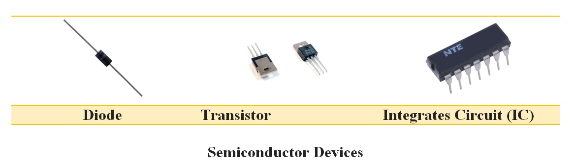
Semiconductor, any of a class of crystalline solids intermediate in electrical conductivity between a conductor and an insulator. Semiconductors are employed in the manufacture of various kinds of electronic devices, including diodes, transistors, and integrated circuits. They are having probable future, the key elements of the majority of electronic systems including communications with data-processing, consumer, and industrial-control equipment.
Semiconductor materials are useful by their behavior which can be easily manipulated by the addition of impurities is known as doping. Semiconductor conductivity can be controlled by the electric or magnetic field, by exposure to light or heat, or by the mechanical deformation of a doped mono crystalline grid; thus, semiconductors can make excellent sensors.
Back to contents
Electricity, Voltage, Current and Resistance
In simple terms, electricity is a form of energy that we can harness and convert into heat, light, movement, and power. Electricity has three main properties that will be important to us as we build projects: current, voltage, and power.
Voltage (pushes the Electrons):
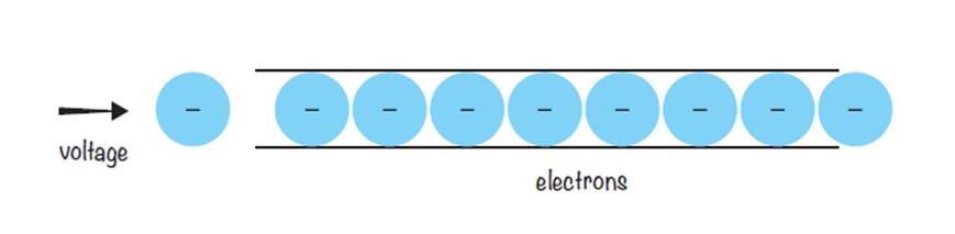
Voltage is the electric force that drives current around an electric circuit. Voltage is a measure of the difference in potential energy between a circuit's positive and negative ends. This is measured in volts (V). The greater the voltage, the faster the current moves through a circuit. A Voltmeter measure the potential difference between two points in volts. A Voltmeter used in parallel.
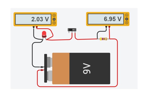
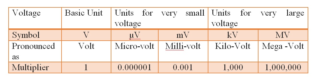
Most cells produce a voltage of about 1.5 V. The voltage of the mains supply is 230 V. At a power station, the voltage is higher and is measured in kilovolts, symbol kV. Small voltages are measured in milli volts, symbol mV. A milli volt is one-thousandth of a volt.
A current flows in a circuit if there is a potential difference (pd) between two points in the circuit. A pd may be produced in many different ways:
- Chemical action: as in an electric cell.
- Electricity generator: uses the energy of burning fuel (coal, oil, gas).
- Nuclear power: uses heat from nuclear reactions.
- Solar cells: use energy from sunlight.
- Wind farm: uses energy from wind.
Current (Flow of Electrons):
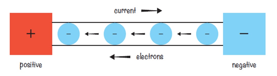
The flow of electrical energy through a circuit is called the current. Electrical current flows through a circuit from the positive side of a power source, such as a battery, to the negative side of the power source. This is known as direct current (DC).
Current is measured in amperes or "amps" (A). Small amounts of current are measured in milliamps (mA), where 1,000 milliamps equal 1 amp. An Ammeter measures current flow in amps. It is inserted into the path of current flow, or in series, in the circuit.
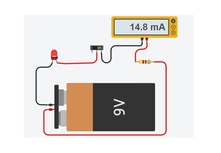
An ampere is defined as 6.241*1018 electrons (1 Coulomb) per second passing through a point in a circuit.
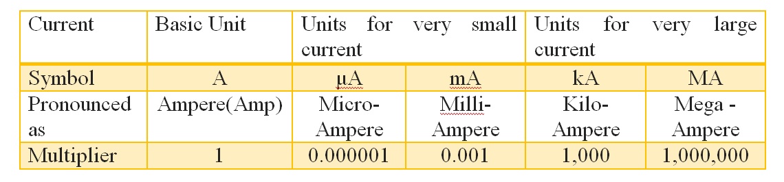
Voltage and Current Comparison

Resistance (Reduces the current)
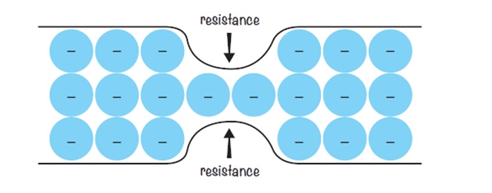
Resistance (also known as ohmic resistance or electrical resistance) is a measure of the opposition to current flow in an electrical circuit.
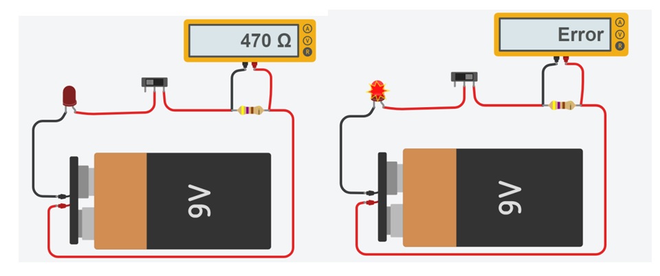
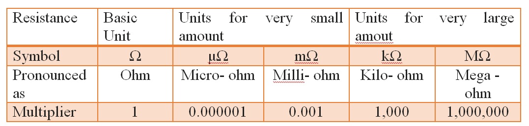
Resistance is measured in ohms, symbolized by the Greek letter omega (Ω).An ohmmeter is used to measure the resistance of a device when no current flows. otherwise the meter resistance bypasses the component due to low resistance, and current in the loop increases. This may damage the components in the circuit.
Fill in the blanks
1. _____________ is the electric force that drives current around an electric circuit.
2. Voltage is measured in ______________.
3. The greater the voltage, ______________the current moves through a circuit.
4. Most cells produce a voltage of about  _______V.
5. The voltage of the mains supply is _______ V.
6. 1000 milli Volt  =  _____________ Volt
7. 1 Kilo Volt = _____________ Volt
8. The flow of electrical energy through a circuit is called the __________.
9. Current is measured in _______________
10. 1000 milli Ampere  =  ______ Ampere.
11. 1000 Ampere  = _________ Kilo Ampere.
12. 500mA = ________ A
13. ____________is a measure of the opposition to current flow in an electrical circuit.
14. Resistance is measured in ___________.
15. 2.2 Kilo ohm = _________ ohm.
16. 5600 ohm = ___________ Kilo Ohm.

Answers
1) Voltage  2)volts (V)  3) the faster  4) 1.5    5) 230   6) 1    7) 1000 8) current
9) amperes or "amps" (A)  10) 1    12) 0.5  13) Resistance  14)  ohms    15) 2200
16) 5.6
Back to contents
Power
Electric power expresses the rate at which an electrical device is converting energy from one form into another. For example a room heater converts electrical energy into heat energy. The rate at which it does this is its power, expressed in watts. The symbol for watt is W.
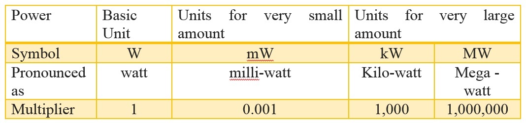
For example, a 100 W light bulb is much brighter than a 60 W bulb because the higher-wattage bulb converts more electrical energy into light.
An average electric lamp runs at 10 W. A typical two-bar heater is rated at 2000 W, or 2 kilowatts. The power of an electrical power station (converting energy from coal into electrical energy) is measured in megawatts.
It can be shown that the power of a device is proportional to the amount of current flowing through it. It is also proportional to the voltage that is driving the current. The bigger the current and the bigger the driving force, the bigger the power.
A simple mathematical relationship exists among voltage, current, and power:
Power (W) = Voltage (V) × Current (A)
Example: A Study lamp runs on a 12 V supply and takes 0.5A. What is its power?
Power = 12x0.5 = 6 Watts.
Fill in the blanks
1)What is the power dissipated by a resistor for the following voltage and
current values?

i)   V = 10 volts,    I = 3 amperes    P = _______ watt
ii)  V = 100 volts,   I = 5 amperes    P = _______ watt
iii) V = 120 volts,   I = 10 amperes   P = _______ watt

2)What is the power dissipated by a resistor given the following resistance
and current values?

i)    R = 20 ohm,    I = 0.5 ampere   P = _______ watt
ii)   R = 560 ohms,  I = 0.02 ampere  P = _______ watt
iii)  R = 300 ohms,  I = 2 ampere     P = _______ watt

3)What is the power dissipated by a resistor given the following resistance
and current values?

i)  V = 10 volt, R = 20 ohms   P =  _______ watt
ii) V = 20 volt, R = 100 ohms  P =  _______ watt
iii) V = 25 volt,R = 100 ohms  P =  _______ watt

Answers
1)  i) 30    ii) 500   iii) 1200
2)  i) 5      ii) 2.24  iii) 1200
3)  i) 5      ii) 4       iii)  6.25
Back to contents
Ohm's Law
Ohm's Law states that the relationship between current, resistance, and voltage is as follows: The current in a circuit is directly propositional to the applied voltage and inversely proportional to the resistance.
voltage (V) = current (I) × resistance (R)
Understanding this relationship is important for fast, accurate electrical problem diagnosis and repair.
If you know two of the quantities, then you can calculate the third. A popular way to remember Ohm's Law is with a triangle.
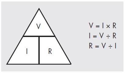
Example: A 12-volt battery produces a current in the circuit of 0.5 A. What is the resistance?
R = V/I = 12 / 0.5 = 24 ohms.
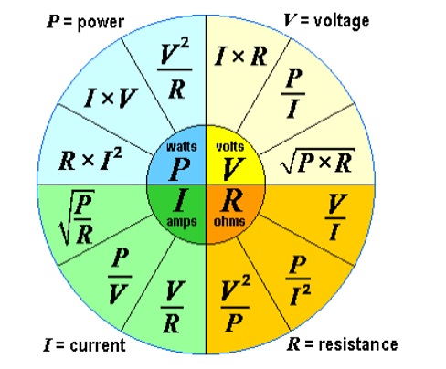
The power wheel calculator
The power wheel calculator simplifies the calculation of all main electric parameters, i.e. voltage, current, power, and resistance; and clarifies the relation between these parameters.
Fill in the blanks
1) What is the algebraic formula for Ohm's law?

A) ______________

2) Find the Resistance for each combination of voltage
   and current values using ohm's law?

i)   V = 5 Volt   I = 2 ampere     R = _________
ii)  V = 9 Volt   I = 1 ampere     R = _________
iii) V = 5 Volt   I = 0.02 ampere  R = _________

3) Find the voltage for each combination of resistance
   and current values using ohm's law?

i)    R = 200 ohm   I = 5 ampere   V = _________
ii)   R = 500 ohm   I = 2 ampere   V = _________
iii)  R = 1000 ohm  I = 1 ampere   V = _________

4) Find the current for each combination of voltage
   and resistance values using ohm's law?

i)    V = 5 Volt   R = 200 ohm   I = _________
ii)   V = 9 Volt   R = 250 ohm   I = _________
iii)  V = 5 Volt   R = 500 ohm   I = _________

Answers
1) V = I x R  2) i) 2.5    ii) 9    iii) 250
3) i)1000   ii)1000  iii)  1000
4) i) 0.025      ii) 0.036   iii) 0.01
Back to contents
Electric Circuit
An electric circuit is a closed path in which electrons move to produce electric currents. Electric circuits are important concepts that have practical applications in our daily lives.
A circuit is a complete path for current when voltage is applied.
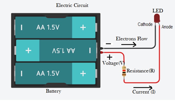
When we provide a path for the battery by connecting a piece of wire from one end of the battery to the other, forming a circuit with a loop of wire, we will initiate a continuous flow of electrons in a clockwise direction. Because of electrons are negative and like charges repel, while unlike charges attract, Electrons flow from negative terminal of the battery to positive terminal of the battery.So long as the battery continues to produce voltage and the continuity of the electrical path isn't broken, electrons will continue to flow in the circuit.
So long as the voltage source keeps "pushing" in the same direction, the electron flow will continue to move in the same direction in the circuit. This single-direction flow of electrons is called a Direct Current, or DC.
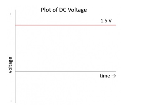
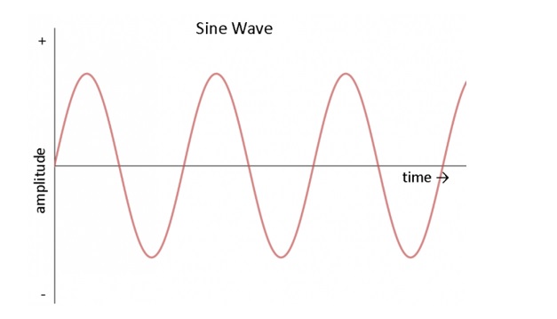
Electric charge in alternating current (AC), on the other hand, changes direction periodically. The voltage in AC circuits also periodically reverses because the current changes direction.
Source of Electrical Energy
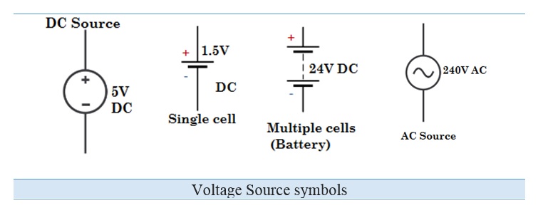
The first component in an electric circuit is the source of electrical energy that allows electrons to move. This source could be a battery, a solar cell, or a hydroelectric plant—a place where there's a positive terminal and a negative terminal and from where charge could flow from one to the other. This push of electric charge is called voltage whose potential is measured in volts.
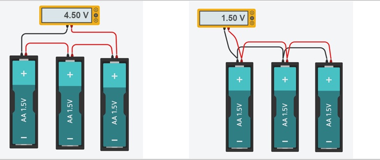
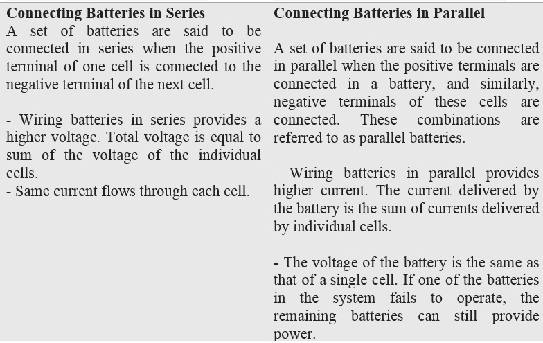
Batteries in series and Parallel:
Short Circuit:
A short circuit is an electric circuit offering little or no resistance to the flow of electrons. When short circuit happens, resistance lessens instantly and a large volume of current flows through an unexpected pathway.
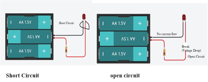
Open Circuit:
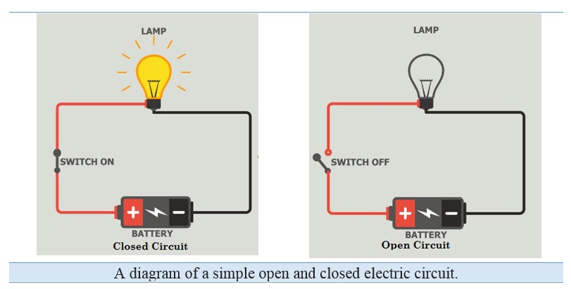
If due to disconnection of any part of an electric circuit if there is no flow of current through the circuit, is said to be an open circuited.
Closed Circuit:
If there is no discontinuity in the circuit and current can flow from one part to another part of the circuit, the circuit is said to be closed circuit.
Some facts about circuit
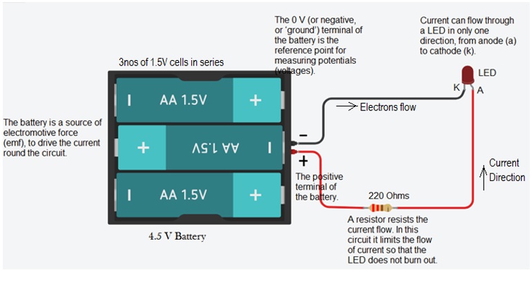
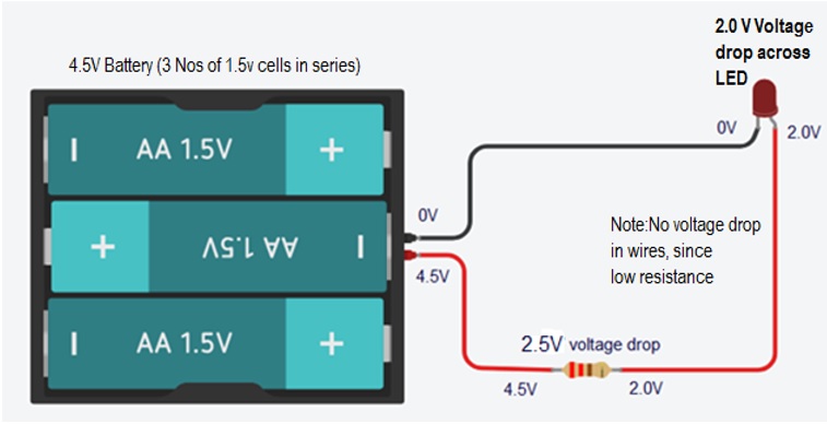
Voltages in the Circuit:
Voltage Drop: Whenever current passes through any component, the voltage is used up. The used is voltage is called Voltage drop.
Energy Conversions in the circuit:
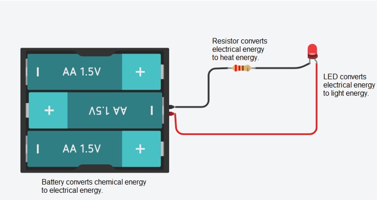
Series and Parallel Circuits
Circuits consisting of just one battery and one load resistance are very simple to analyze, but they are not often found in practical applications. Usually, we find circuits where more than two components are connected together. There are two basic ways in which to connect more than two circuit components: series and parallel.
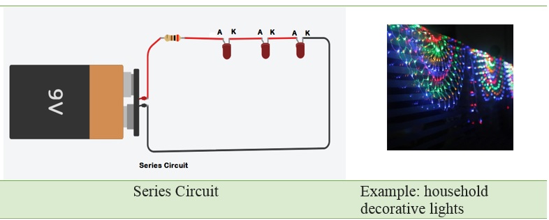
Series Circuit:
In a series circuit, all components are connected end-to-end, forming a single path for current flow. Let us consider the household decorative string lights as an example of a series circuit. This is nothing but a series of multiple tiny bulbs connected in series. If one bulb fuses or circuit breaks, current not able to flow, all the bulbs in series do not light up.
Observations in the Series Circuit:
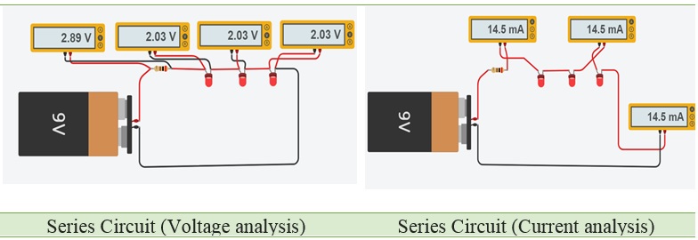
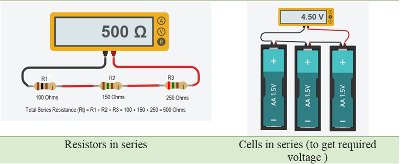
Current: The amount of current is the same through any component in a series circuit.
Resistance: The total resistance of any series circuit is equal to the sum of the individual resistances.
Voltage: The supply voltage in a series circuit is equal to the sum of the individual voltage drops. The largest resistor has the largest voltage.
Parallel Circuit:
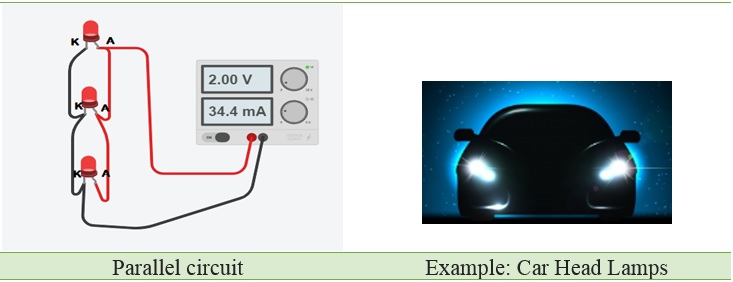
A circuit is called a Parallel Circuit when two or more components are connected to the same node and both the sides of the components are connected directly to the battery or any other source. The current in a Parallel-Circuit has two or more paths to flow through it.
The most common example of Parallel-Circuit is the wiring of car headlights. In case the car headlights were in series, then if one of the lights fail, the other would also turn off which means the safety factor is lost.
Observations in the Parallel Circuit:
Resistors in parallel
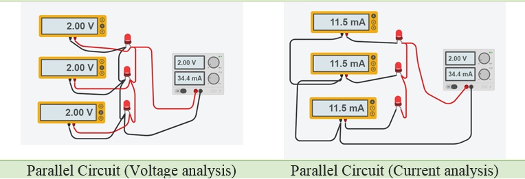
Current: The total circuit current is equal to the sum of the individual branch currents. The largest share current flows through the smallest resistance.
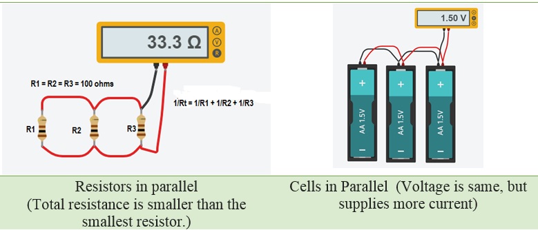
Resistance: Total resistance in a parallel circuit is less than any of the individual resistances.
Voltage: The Voltage is equal across all components in a parallel circuit.
Components of a Circuit
All Circuits require the following Components: Power source, Protection Device, Control Device, Load, Conductors and Ground.
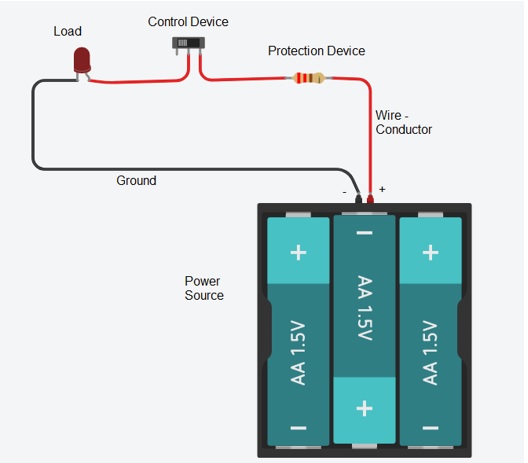
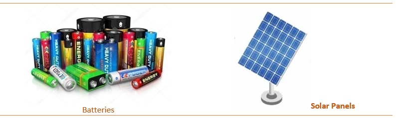
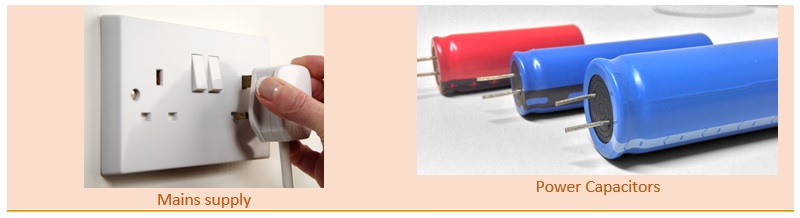
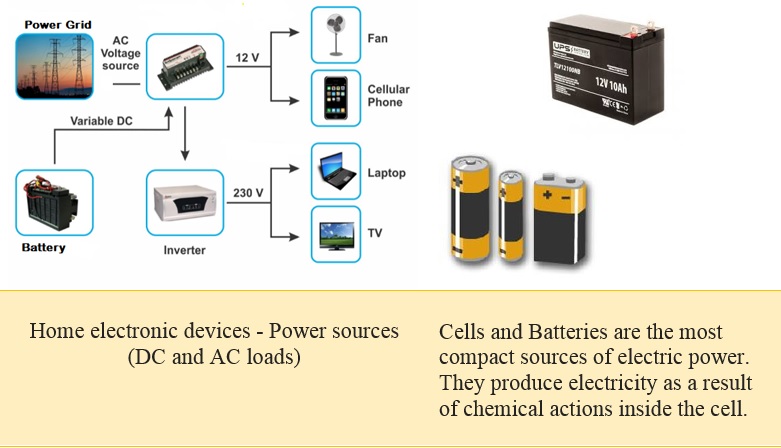
Power Source: A power source is a source of Power to the circuit. Most commonly the type of power referred to is battery. All electronic projects need a source of electrical power. This supplies the charged electrons which make electronic circuits work.
Protection Device: Protection device is required to protect the circuit from excessive current and voltages. Excessive current generates heat can damage wires and electronic components. Fuses and Fusible links can protect circuits by opening the circuit path when there is too much current. A Varistor or VDR (voltage dependent resistor) is used to protect the circuits from excessive voltages.
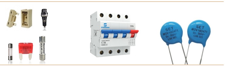
Fuse used to protect the circuit from over current.
MCBMiniature Circuit Breaker - It automatically switches OFF electrical circuit during overload & short circuit conditions.
MOV Metal Oxide Varistor - used to protect the circuit from high voltage spikes by varying its resistance.
Control Device: Control in device is used to regulate the operation of a circuit, apparatus, or system. The simplest control device is as switch. A control can do more than just turn the load on and off. It can also regulate the load by varying the current.
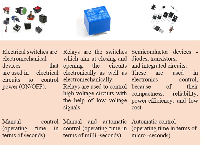
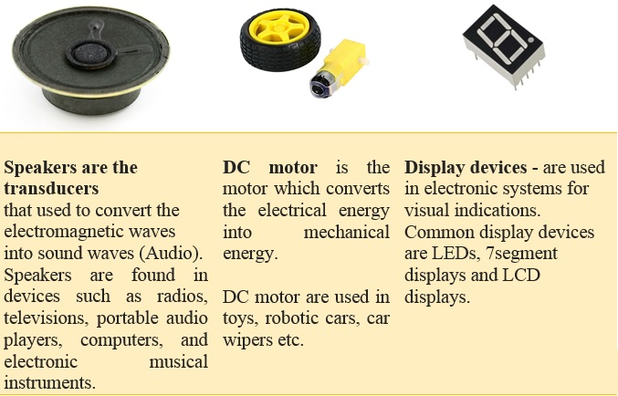
Load: The reason we want to build circuits is to make electricity do useful things for us. The way we do that is by putting things in the circuit that use the current flow to light up, make noise, run programs, etc. These things are called loads, because they “load down” the power supply, just like you're “loaded down” when you're carrying something.
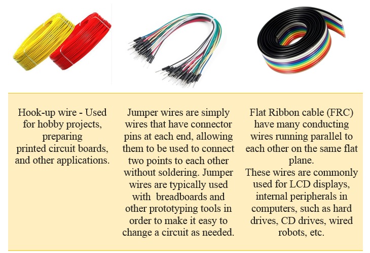
Conductors: Conductors are materials that allow electric current to flow through them. Conductors are used to inter-connect the electronic components.
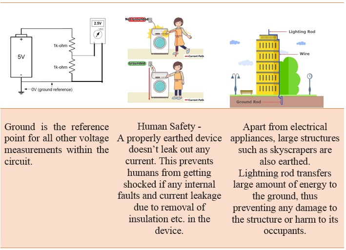
Ground: In electrical engineering, ground or earth is the reference point in an electrical circuit from which voltages are measured, a common return path for electric current, or a direct physical connection to the earth.
Back to contents
Light Emitting Diodes (LEDs)
Light Emitting Diodes (LEDs) - A type of diode that illuminates when electricity passes through it. Like all diodes, electricity only flows in one direction through these components. You're probably familiar with these as indicators on a variety of electronic devices.
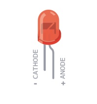
An LED, or light-emitting diode, is a component that converts electrical energy into light energy. LEDs are polarized components, which means they only allow electricity to flow through them in one direction. The longer leg on the LED is called an anode, it will connect to power. The shorter leg is a cathode and will con¬nect to ground. When voltage is applied to the anode of the LED, and the cathode is connected to ground, the LED emits light.
Testing a LED:
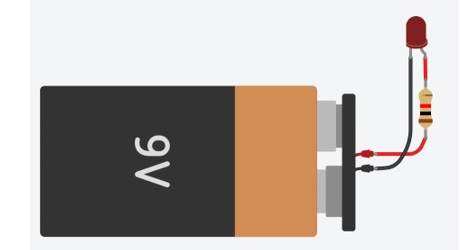
Never connect an LED directly to a battery or power supply because the LED is likely to be destroyed by excessive current passing through it. LEDs must have a resistor in series to limit the current to a safe value, for testing purposes a 220 resistor is suitable for most LEDs if your supply voltage is 5V.
Series Resistance Value Calculation:
To calculate the required current-limiting resistor for an LED, use this formula:
 R = (Vs − Vf) ÷ I

where Vs is the supply voltage (5 V);
      Vf is the LED forward voltage drop (say, 1.7 V),
      and I is the current required for the LED (15 mA).
     (The value of I must be in amps, so
	 10 mA converts to 0.01 A.)
Now let's use this for our LEDs—with a value of 5 V for Vs , 1.7 V for Vf ,and 0.015 A for I. Substituting these values into the formula gives a value for R of 220 ohms.
LEDs advantages:
LEDs have many advantages over incandescent light sources, including lower energy consumption, longer lifetime, improved physical robustness, smaller size, and faster switching.
LEDs Applications:
LEDs are used in automotive headlamps, advertising displays, general lighting, traffic signals, camera flashes and industrial devices.
Bi-Color Light Emitting Diodes:
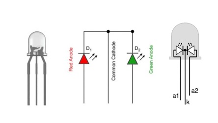
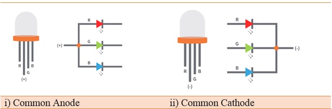
The Bi-color LED is a handy little component that allows two colors (red, green) in a single LED having three pins (cathode and red, green). The color of the LED depends on the input given to the red or green pin.
The bi-color light emitting diodes are a type of LEDs similar to single color LEDs just with additional one more LED chip enclosed in the package. It Contains two LEDs in one package. In general, the two LED leads are connected in inverse parallel combination. The anode of one LED is connected to the cathode of another LED and vice versa. When the supply is given to either of the anode only one LED will glow. We can also turn on both LEDs at same time with dynamic switching at high speed.
Tri-Color LED:
This type of LED has three leads enabling any combination of LEDs to be light, i.e. the first LED, the second, or both. The most popular form of tri-colour LED uses a red and green diode. This means that when one diode is on, then either red or green is produced. If both are light, then the colours combine to form yellow.
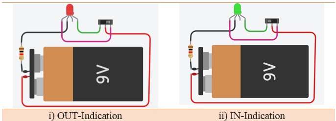
IN/OUT Indicator using multi-color LED:
Back to contents
Resistors
Various components, such as the LED, require only a small amount of current to function—usually around 10 mA. When the LED receives excess current, it converts the excess to heat—too much of which can kill an LED. To reduce the flow of current to components such as LEDs, we can add a resistor between the voltage source and the component. Current flows freely along normal copper wire, but when it encounters a resistor, its movement is slowed. Some current is converted into a small amount of heat energy, which is proportional to the value of the resistor.
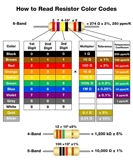
Resistors - A resistor is a component that adds resistance to a circuit. The more resistance your circuit has, the less current will flow through it. Resist the flow of electrical energy in a circuit, changing the voltage and current as a result. Resistor values are measured in ohms (represented by the Greek omega char¬acter: Ω). The colored stripes on the sides of resistors indicate their value.
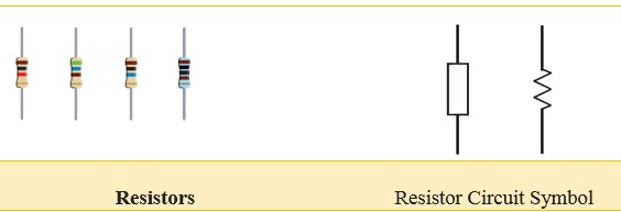
The photo shows a typical fixed resistor. Resistors of this kind are sold in a range of different resistances, from less than 1 Ω and up to 10MΩ.
Resistors in Series:
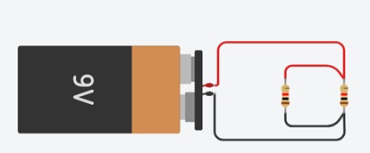
A set of resistors are said to be in series when they are connected back to back in a single line. The same current will flow through all the resistors. Resistors in series are said to have common current.

If RT is the total resistance, then RT = R1 +R2 +R3
Applications:
When two resistors of different resistances are connected in series, the voltage across them is different. This method is the basis for voltage divider circuits.
Voltage Divider Circuit:
Resistors in Parallel:
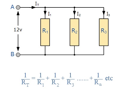
Two resistors are said to be connected in parallel if both the terminals of a resistor are connected to each respective terminal of other resistor. In a network of parallel resistors, current can take more than one path unlike in series resistor network as there are multiple paths for the current to flow. Hence parallel resistor circuits are current dividers.
Applications:
The concept of resistors in parallel is used in the analysis of Wheatstone bridge circuit. Resistors in parallel combination act as Current Divider Circuit. This current divider concept is use full in applications like Analog to Digital Converters and Digital to Analog Converters.
Current Divider Circuit::
Variable Resistors
Variable resistors consist of a resistance track with connections at both ends and a wiper which moves along the track as you turn the spindle. The track may be made from carbon, cermet (ceramic and metal mixture) or a coil of wire (for low resistances). The track is usually rotary but straight track versions, usually called sliders, are also available.
A Variable Resistor may be used instead of a fixed resistor where variable resistance is required.
A Variable Resistor is a useful device, because by just simply adjusting it, it can be used to represent a wide range of resistances in a circuit from anywhere near 0Ω to the specified resistance rating of the potentiometer. Therefore, for example, a 10KΩ potentiometer can be adjusted to give the resistance range from almost 0Ω to 10KΩ by adjusting the potentiometer knob.
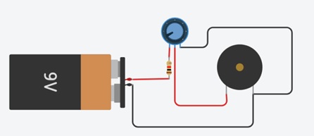
Volume Control Circuit (potentiometer):
Variable resistors used as potentiometers have all three terminals connected. This arrangement is normally used to vary voltage.
LED Brightness Control (Rheostat):
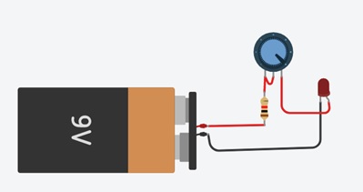
This is the simplest way of using a variable resistor. Two terminals are used. Rheostats are often used to vary current.
Capacitor
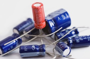
A capacitor is a device that holds an electric charge. It consists of two metal plates with an insulating layer that allows an electric charge to build up between the plates. Once the current is stopped, the charge remains and can flow out of the capacitor (called discharging the capacitor) as soon as the charge voltage stored in the capacitor is presented with a new path for the current to take.
Measuring the Capacity of a Capacitor:
The amount of charge that a capacitor can store is measured in farads, and one farad is actually a very large amount. Therefore, you will generally find capacitors with values measured in picofarads or microfarads.
One picofarad (pF) is 0.000000000001 of a farad, and one microfarad (μF) is 0.000001 of a farad. Capacitors are also manufactured to accept certain voltage maximums. In this book, we'll be working with low voltages only, so we won't be using capacitors rated at greater than 10 V or so; it's generally fine, however, to use higher-voltage specification capacitors in lower-voltage circuits. Common voltage ratings are 10, 16, 25, and 50 V.
Charging and Discharging of a capacitor:
When positive and negative charges applied on the capacitor plates, the capacitor becomes charged. A capacitor can retain its electric field -- hold its charge -- because the positive and negative charges on each of the plates attract each other but never reach each other.
At some point the capacitor plates will be so full of charges that they just can't accept any more. There are enough negative charges on one plate that they can repel any others that try to join. This is where the capacitance (farads) of a capacitor comes into play, which tells you the maximum amount of charge the cap can store.
If a path in the circuit is created, which allows the charges to find another path to each other, they'll leave the capacitor, and it will discharge.
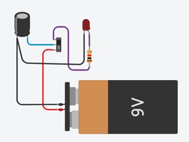
For example, in the circuit below, a battery can be used to induce an electric potential across the capacitor. This will cause equal but opposite charges to build up on each of the plates, until they're so full they repel any more current from flowing. An LED placed in series with the cap could provide a path for the current, and the energy stored in the capacitor could be used to briefly illuminate the LED.
Calculating Charge:
A capacitor's capacitance -- how many farads it has -- tells you how much charge it can store. How much charge a capacitor is currently storing depends on the potential difference (voltage) between its plates. This relationship between charge, capacitance, and voltage can be modeled with this equation:

Charge (Q) stored in a capacitor is the product of its capacitance (C) and the voltage (V) applied to it.
The capacitance of a capacitor should always be a constant, known value. So we can adjust voltage to increase or decrease the cap's charge. More voltage means more charge, less voltage...less charge.
That equation also gives us a good way to define the value of one farad. One farad (F) is the capacity to store one unit of energy (coulombs) per every one volt.
Back to contents
Manual Control Device - Electrical Switches
A device designed to open or close a circuit under controlled conditions is called a switch.Switches are used to control the flow of current in a circuit. Current flows when the switch contacts come together. We say that the switch is closed, or contact is made. Current cannot pass through the switch when the contacts are apart. We say that the switch is open, or contact is broken.
The schematic symbols for two different types of switches are shown below:

Normally Open Push Button:
A Normally Open (NO) Push Button is a push button that, in its default state, makes no electrical contact with the circuit. Only when the button is pressed down does it make electrical contact with the circuit.
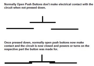
When the button is pressed down, the switch makes electrical contact and the circuit is now closed. Therefore, electricity can now flow to the other part of the circuit connecting to the push button and make the device turn or power on the respective part.
Normally Open Push buttons are the most common type of push buttons used in devices and circuits.
Normally Closed Push Button:
A Normally Closed (NC) Push Button is a push button that, in its default state, makes electrical contact with the circuit.
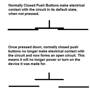
When the button is pressed down, the switch no longer makes electrical contact and the circuit is now open. Therefore, electricity can no longer flow to the other part of the circuit to turn or power on the respective part of the circuit the button was made to switch.
Normally Closed Push buttons are not the most common type of push button used; Normally Open Push Buttons are. However, they still have widespread use and application in many devices.
Commonly used switches in Electronic Projects:
Toggle Switch:
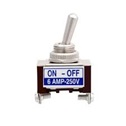
A toggle switch is a basic switch, operated by a toggle lever that can be pushed up or down. By convention, the down position is the ‘on', or ‘closed', or ‘made' position. The toggle switch in the photo has its toggle lever up. Behind the lever is a threaded dolly with a large nut. This is for mounting the switch in a circular hole cut in a panel.
Pushbuttons Switches:
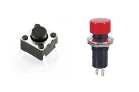
A push switch is operated by pressing a button. There are two types of action. Most switches are push-to-make (or PTM) switches. Pressing the button pushes the contacts together and the switch closes. The other type are push-to-break (or PTB) switches. The contacts are normally closed but are forced apart when the button is pressed. Either type of switch may be momentary or latching.
Slide Switch:
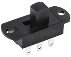
Slide switches are mechanical switches using a slider that moves (slides) from the open (off) position to the closed (on) position. Slide switches are maintained-contact switches. Maintained-contact switches stay in one state until actuated into a new state and then remain in that state until acted upon once again.
Switch Wiring Schemes
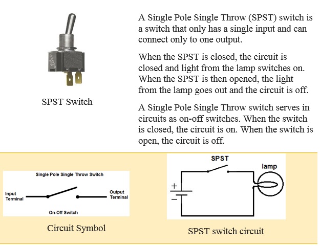
Single Pole Single Throw (SPST) Switch:
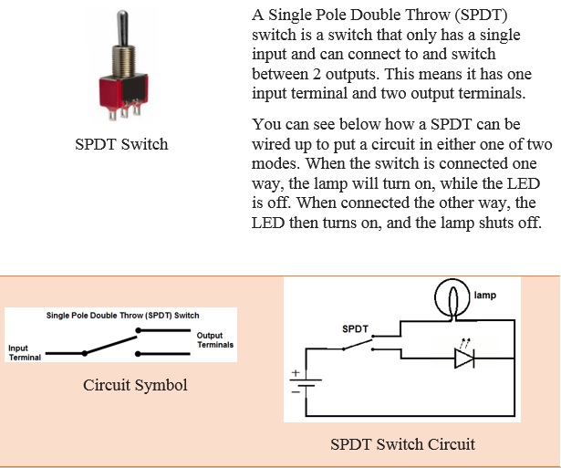
Single Pole Double Throw (SPDT) Switch:
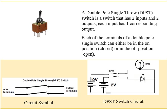
Double Pole Single Throw (DPST) Switch:
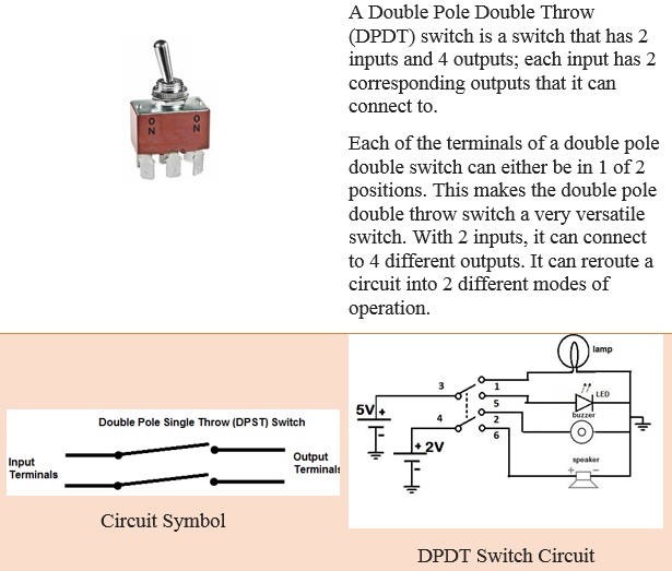
Double Pole Double Throw (DPDT) Switch:
Switches in series and in parallel
are two ways of connecting two switches into a circuit:
(a) series – one after the other
(b) parallel – side by side
You can see the two versions in the following diagrams
(a) series circuit
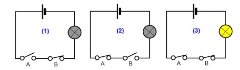
The lamp will only light up when switch A AND switch B are closed (diagram 3).
(b) parallel circuit
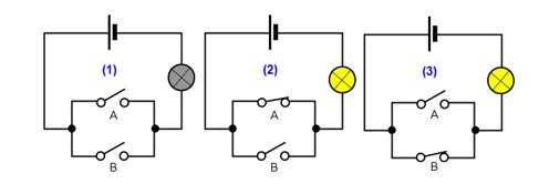
In this circuit the lamp will light up when switch A OR switch B OR both are closed.
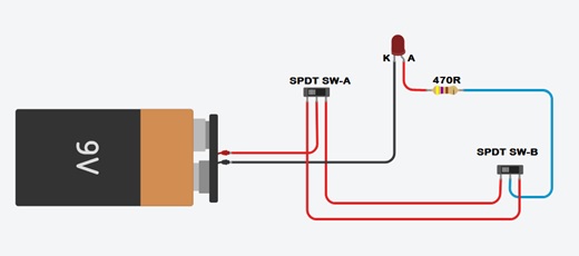
Staircase Wiring circuit diagram & working:
Staircase wiring is a common multi-way switching or two-way light switching connection; one LED two switches wiring. Here one LED is controlled by two switches from two different positions. That is to operate the lamp from separate locations such as above or below the staircase, from inside or outside of a room, or as a two-way bed switch, etc.
Back to contents
Electrical Control device - Relay
Relay is an electromechanical switching device most widely used in the automotive and telecommunication industries. It can be found in cars, washing machines, medical equipment, aircraft, etc. We can see that relays are being used in control systems and power systems industries to protect the system or load circuit from unexpected damage.
A switch is a component that opens (turn off) & close (turn on) an electrical circuit manually. whereas, a relay is an electrical switch that control (switch on & off) a high voltage circuit using a low voltage source. A relay completely isolates the low voltage circuit from the high voltage circuit. Relays can be controlled electronically. Relay operates faster than switches.
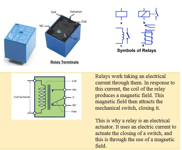
Terminals of a Relay
Control Input or Coil Terminals:
Control input terminals are two input terminals of a relay that controls its switching mechanism. A low power source is connected to these terminals to activate & deactivate the relay.
NO Terminal:
NO or Normally Open terminal is also a load terminal of a relay which remains open when the relay is not active.
NC Terminal:
NC or Normally Closed terminal is the other load terminal of a relay. This terminal is normally connected with COM terminal of the relay when there is no control input.
COM or Common Terminal:
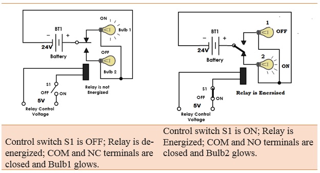
It is the terminal of the relay where you connect the first part of your circuit. When the relay is powered, and the switch is closed, the common terminal and the normally open terminal have continuity. On the other hand, when the relay is not powered, and the switch is open, the common terminal and the normally closed terminal have continuity.
Back to contents
Diode
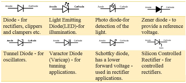
A diode is made of silicon. Silicon is neither an insulator nor a conductor. It is a semiconductor. A diode functions as the electronic version of a one-way valve. By restricting the direction of movement of charge carriers, it allows an electric current to flow in one direction, but blocks it in the opposite direction.
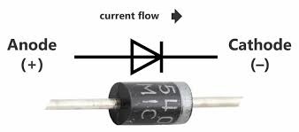
Diode is made of P and N type materials and has two terminals namely anode and cathode. This device can be operated by controlling the voltage applied to these terminals. When the voltage applied to the anode is positive with respect to the cathode, the diode is said to be in Forward Bias. If the voltage applied to the diode is greater than the threshold level (generally, it is of ≈0.6V for Silicon Diodes), then diode acts as a short circuit and allows the current flow. If the polarity of the voltage is changed i.e., the cathode is made positive with respect to anode, then it is said to be in Reverse Bias and acts as open circuit. As a result, no current flows through it.
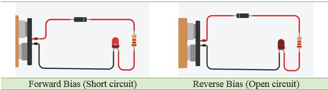
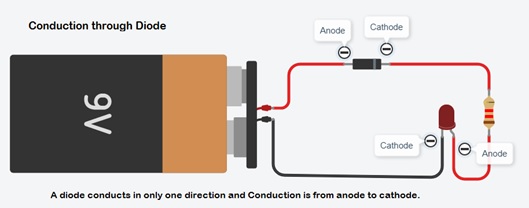
Since electricity can only flow in one direction through a diode they must be connected correctly. Electrical current flows from the cathode side of a diode to the anode side. Generally the cathode side is connected to the negative side of a DC power supply. A diode has a black band marking the cathode side.
Voltage drop across diode:
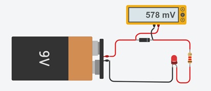
A forward biased diode has a voltage drop of about 0.7 V. This voltage drop is called the forward voltage drop.
How to Test Diodes with a Digital Multi-meter:
Digital multi-meters can test diodes using one of two methods:
1.Diode Test mode: almost always the best approach.
2.Resistance mode: typically used only if a multi-meter is not equipped with a Diode Test mode.
Note: In some cases it may be necessary to remove one end of the diode from the circuit in order to test the diode.
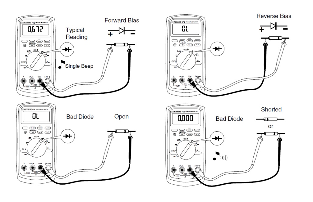
A diode is best tested by measuring the voltage drop across the diode when it is forward-biased. A forward-biased diode acts as a closed switch, permitting current to flow. A multi-meter's Diode Test mode produces a small voltage between test leads. The multi-meter then displays the voltage drop when the test leads are connected across a diode when forward-biased.
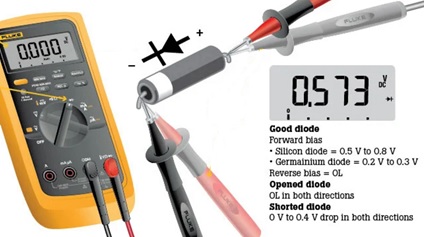
A multi-meter set to the Resistance mode (Ω) can be used as an additional diode test or, as mentioned previously, if a multi-meter does not include the Diode Test mode.
Diodes applications:
The application areas of diodes include communication systems as limiters, clippers, gates; computer systems as logic gates, clampers; power supply systems as rectifiers and inverters; television systems as phase detectors, limiters, clampers; radar circuits as gain control circuits, parameter amplifiers, etc.
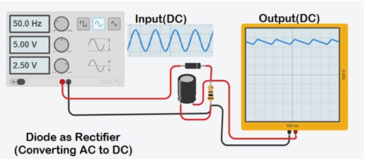
Diode as Rectifier:
This circuit is used to transform AC waveform into DC waveform.
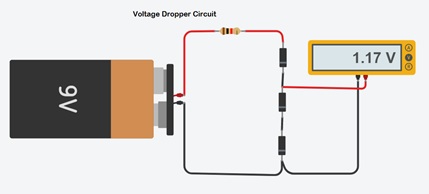
Voltage Dropper Circuit:
This circuit will drop the power supply voltage by ≈0.6V per diode.
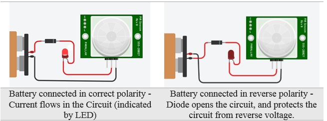
Reverse polarity protector:
Diode protects circuit if battery is installed with reverse polarity.
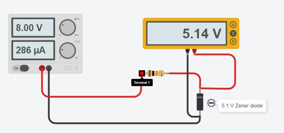
Zener diode voltage regulator:
Zener diodes are widely used as voltage references and as shunt regulators to regulate the voltage across small circuits. When connected in parallel with a variable voltage source so that it is reverse biased, a Zener diode conducts when the voltage reaches the diode's reverse breakdown voltage. From that point on, the low impedance of the diode keeps the voltage across the diode at that value.
The Zener diode behaves just like a normal general-purpose diode consisting of a silicon PN junction and when biased in the forward direction, that is Anode positive with respect to its Cathode, it behaves just like a normal signal diode passing the rated current.
Back to contents
Transistor
The transistor works like an electronic switch. A transistor is similar to a relay in the sense that you can use it to turn something ON and OFF. It can also be used for amplification, switching, voltage stabilization, signal modulation and many other functions.
It is made of semiconductor material. Transistors are found in most electronic devices. The transistor was a major advancement after the triode tube, with using much less electricity, and lasting many years longer, to switch or amplify another electronic current.
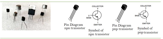
Types of transistor
There are two types of standard (bipolar junction) transistors, NPN and PNP, with different circuit symbols. The letters refer to the layers of semiconductor material used to make the transistor. Most transistors used today are NPN because this is the easiest type to make from silicon. The leads are labeled as base (B), collector (C) and emitter (E). These terms refer to the internal operation of a transistor.
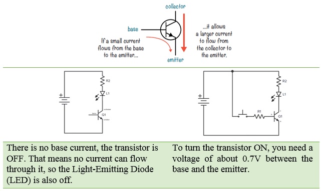
How Transistors Work (NPN type)
When a little bit of current flows from the base of a transistor to the emitter, the transistor "closes the switch" so that current can also flow from the collector to the emitter.
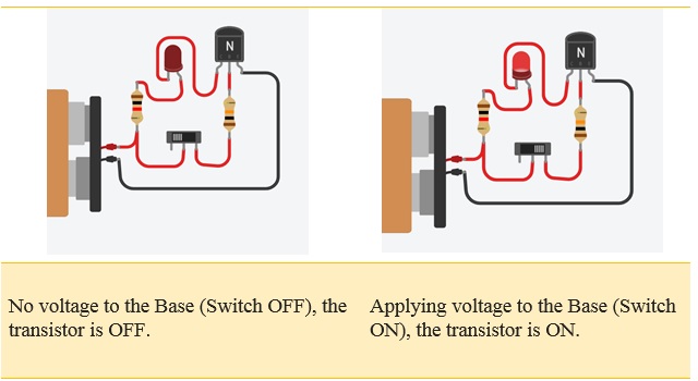
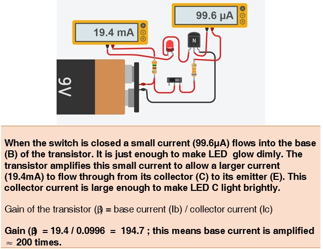
Transistor currents and Gain:
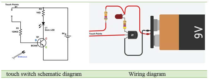
Transistor application circuits
Simple touch switch:The LED in the circuit lights up, when someone touchesthe two endpoints in the circuit, and it turns off when the finger is removed.
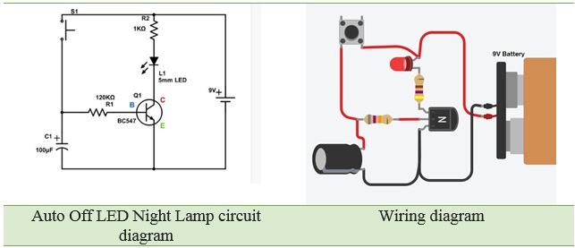
Auto Off LED Night Lamp: You can use this circuit as a night lamp when going to sleep! When you touch the positive terminal of the 9V battery to the positive pole of the capacitor in the circuit, the LED lights up. It remains ON for some time delay and then fades away. The time taken for the LED to turn-off is determined by the value of this capacitor.
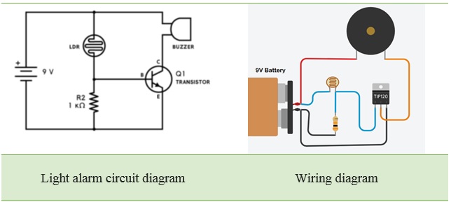
Light Alarm:You can use this circuit as a wakeup alarm.
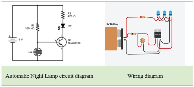
Automatic Night Lamp:You can use this circuit as a study lamp. This lamp automatically turns ON, when sunlight fails.
Back to contents
Integrated Circuits (ICs)
Integrated circuit:
Integrated circuit (IC), also called microelectronic circuit, microchip, or chip, an assembly of electronic components, fabricated as a single unit, in which miniaturized active devices (e.g., transistors and diodes) and passive devices (e.g., capacitors and resistors) and their interconnections are built up on a thin substrate of semiconductor material (typically silicon). The resulting circuit is thus a small monolithic “chip,” which may be as small as a few square centimetres or only a few square millimetres. The individual circuit components are generally microscopic in size.
The advantages of ICs:
(i) Extremely small in size, (ii) Low power consumption, (iii) Reliability, (iv) Reduced cost, (v) Very small weight and (vi) Easy replacement.
The 555 IC:
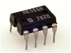
The 555 timer is an integrated circuit, it is extremely versatile and can be used to build lots of different circuits.The EN555 is usually used to generate continuous series of pulses. These series of pulses allow you to continuously blink an LED, for example.
The 555 timer IC was first introduced around 1971 by the Signetics Corporation as the SE555/NE555 and was called "The IC Time Machine" and was also the very first and only commercial timer IC available. It provided circuit designers with a relatively cheap, stable, and user-friendly integrated circuit for both monostable and astable applications.
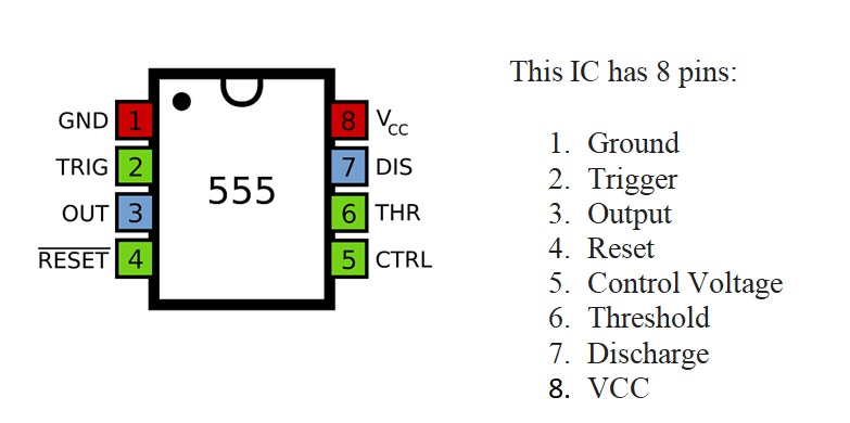
Pin Diagram:
Output :
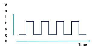
Pin 3 is the output. This pin generates an oscillation. The voltage is high, then low, then high, then low again and so on (this is called astable mode).
ICs and Datasheets
Some ICs have only 8 pins, but other ICs have more than 100! To figure out what each pin on a specific IC does, you need to check that IC's datasheet. The datasheet tells you the function of each pin, specifications and datasheets often show examples of how to use ICs in a circuit, too.
Specifications of the 555 IC timer:
- It operates from a wide range of power ranging from +5 Volts to +18 Volts supply voltage.
- Sinking or sourcing 200 mA of load current.
- The external components should be selected properly so that the timing intervals can be made into several minutes along with the frequencies exceeding several hundred kilohertz.
- The output of a 555 timer can drive a transistor-transistor logic (TTL) due to its high current output.
- It has a temperature stability of 50 parts per million (ppm) per degree Celsius change in temperature which is equivalent to 0.005 %/ °C.
- The duty cycle of the timer is adjustable.
- Also, the maximum power dissipation per package is 600 mW and its trigger and reset inputs has logic compatibility.
555 timer working:
The 555 generally operates in 3 modes:
Astable
Mono-stable
Bi-stable modes.
Astable mode:
This means there will be no stable level at the output. So the output will be swinging between high and low. This character of unstable output is used as a clock or square wave output for many applications.
555 IC LED Flasher (Astable Mode):
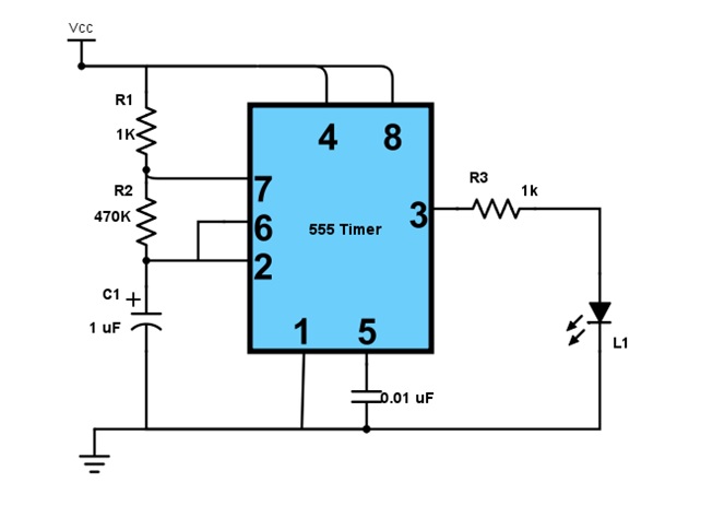
Mono-stable mode:
This configuration consists of one stable and one unstable state. The stable state can be chosen either high or low by the user. If the stable output is set at high (1), the output of the timer is high (1). At the application of an interrupt, the timer output turns low (0). Since the low state is unstable it goes to high (1) automatically after the interrupt passes. Similar is the case for a low stable monostable mode.
555 IC Timer circuit(Monostable Mode):
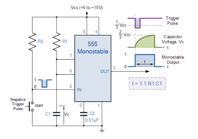
Bi-stable mode:
In bistable mode, both the output states are stable. At each interrupt, the output changes from low (0) to high (1) and vice versa, and stays there. For example, if we have a high (1) output, it will go low(0) once it receives an interrupt and stays low (0) till the next interrupt changes the status.
555 IC memory cell(Bi-stable Mode):
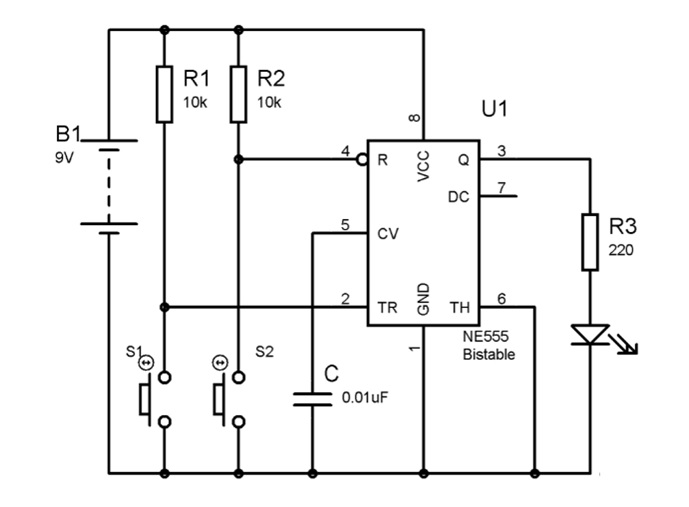
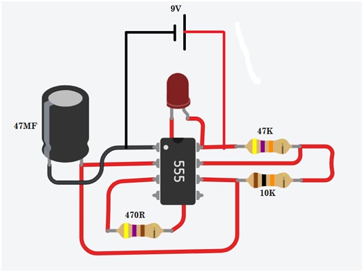
Electronic Fire-fly using555 IC
LM358 Dual Operational Amplifiers
The LM358 IC is a great, low power and easy to use dual channel op-amp IC. It is designed and introduced by national semiconductor. It consists of two internally frequency compensated, high gain, independent op-amps. This IC is designed for specially to operate from a single power supply over a wide range of voltages. The LM358 IC is available in a chip sized package and applications of this op amp include conventional op-amp circuits, DC gain blocks and transducer amplifiers. LM358 IC is a good, standard operational amplifier and it is suitable for your needs. It can handle 3-32V DC supply & source up to 20mA per channel.
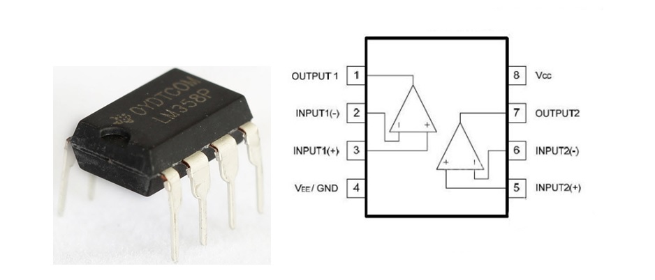
Pin Configuration of LM358 IC
The pin diagram of LM358 IC comprises of 8 pins, where
- Pin-1 and pin-8 are o/p of the comparator
- Pin-2 and pin-6 are inverting inputs
- Pin-3 and pin-5 are non inverting inputs
- Pin-4 is GND terminal
- Pin-8 is VCC+
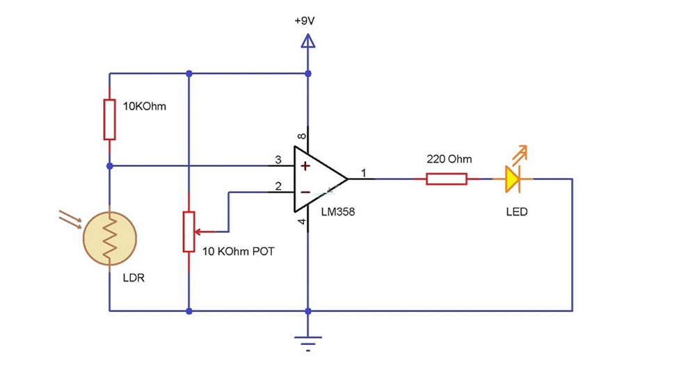
Light Detector using LM358
Back to contents
Measuring Electrical Parameters
A meter is any device built to accurately detect and display an electrical quantity in a form readable by a human being. Usually this "readable form" is visual: motion of a pointer on a scale, a series of lights arranged to form a "bargraph," or some sort of display composed of numerical figures.
In the analysis and testing of circuits, there are meters designed to accurately measure the basic quantities of voltage, current, and resistance.
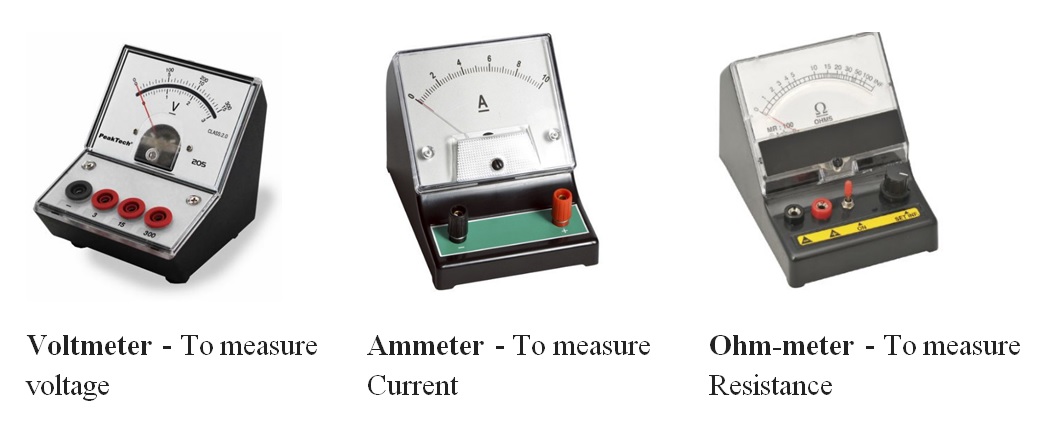
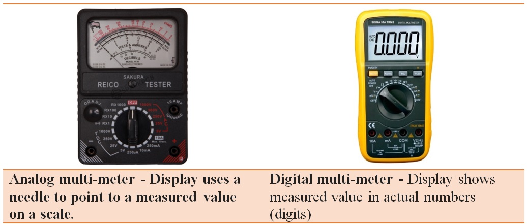
These three metering functions are combined into a single meter called a "Multi-meter". A multi-meter, also known as a volt-ohm meter, is a handheld tester used to measure electrical voltage, current (amperage), resistance, and other values.
Multi-meters come in analog and digital versions and are useful for everything from simple tests, like measuring battery voltage, to detecting faults and complex diagnostics. They are one of the tools preferred by electricians for troubleshooting electrical problems on motors, appliances, circuits, power supplies, and wiring systems.
Multi-meter Functions
Multi-meters are capable of many different readings, depending on the model. Basic testers measure voltage, amperage, and resistance and can be used to check continuity, a simple test to verify a complete circuit. More advanced multi-meters may test for all of the following values:
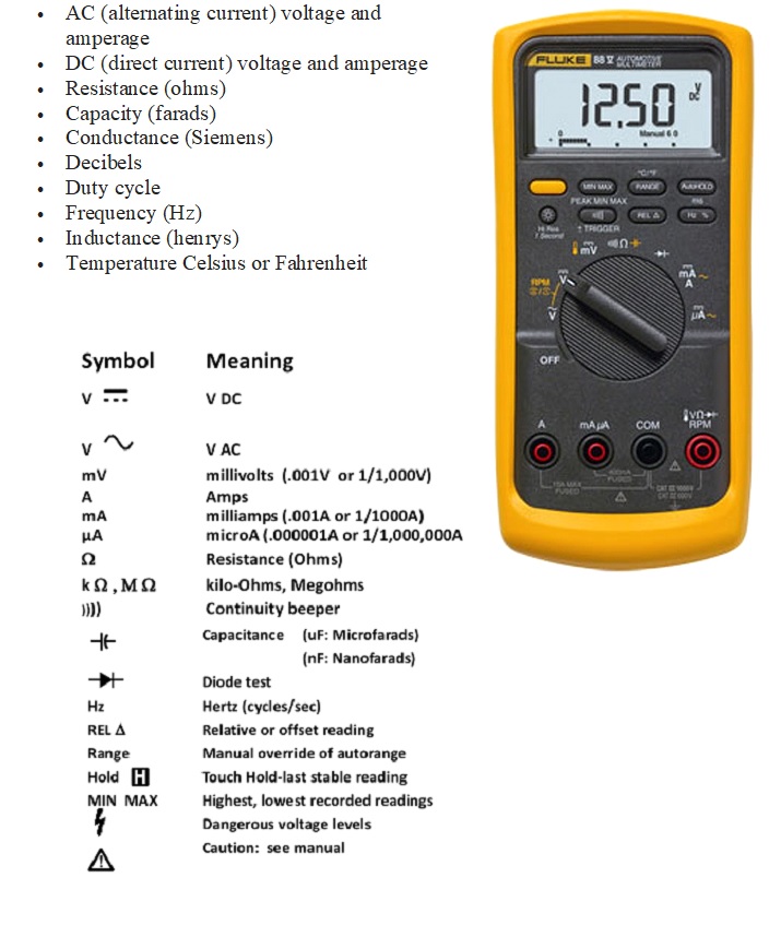
Multi-meter Parts
The multi-meter consists of a digital display, mode selector, range selector, various buttons, test probes & input jacks.
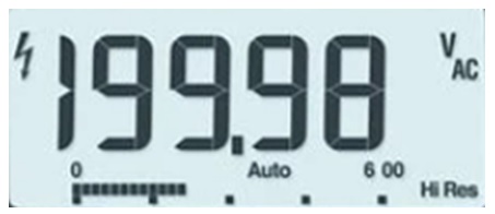
Digital display: The digital display gives a direct readout in actual numbers. However, we must properly interpret to get the correct measured value (i.e Voltage type-AC/DC voltage, Range- mV/mA/V/A and Units - Ohms, V and A etc.
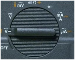
Mode Selector: Mode selector is used to set the meter for the type of test to be performed (i.e DC Volts, AC Volts, milli Volts, Resistance, Continuity test, Diode Check, milli Amps etc)
Range selection & Various Buttons:
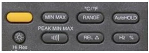
Function button: Yellow button activates secondary functions shown in yellow icons around the dial (often temperature and capacitance).
Min Max: Stores input values; beeps when a value is breached and a new value is set. Peak Min Max: Captures intermittent or transient events that occur on a monitored signal; captures the highest value in a very short duration (microseconds).
Range: Switches to manual mode and cycles through all ranges. Auto ranging restored when pressed for two seconds.
Hold: Captures and holds a stable measurement. AutoHOLD: Captures a measurement, beeps, and locks the measurement on the display for later viewing. Automatically updates with a new stable reading.
Brightness: Switches display backlight between off, low and high.
Audible signal: Activates continuity beeper.
Relative (REL) mode: Stores existing reading (a delta) and resets display to zero. Sets a relative reference point to measure against the next reading.
Test Probes and Input Jacks:
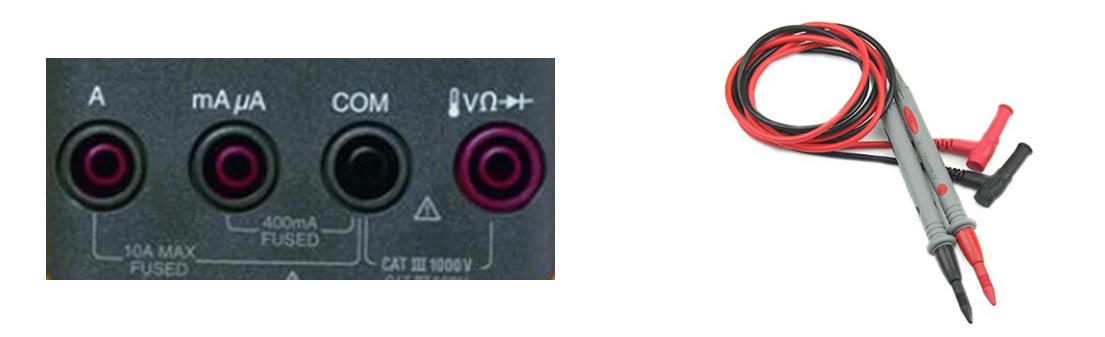
The typical DMM has two test leads and four input jacks. The leads plug in as follows:
BLACK: always plug into the COM input jack.
RED: Plug into the one of the three remaining jacks, depending on what measurement is being performed.
- V/Ω/Diode input for measuring voltage, resistance and Diode checking.
- A input for measuring current upto 10 amps.
- μA/mA input for measuring current upto 400mA.
Measuring voltage
Voltage measurements are made by connecting the DMM in parallel with the measuring point.
If you're measuring DC voltage (such as a battery or a sensor hooked up to an Arduino) you want to set the knob where the V has a straight line (i.e DC). AC voltage (like what comes out of the wall) can be dangerous, so we rarely need to use the AC voltage.
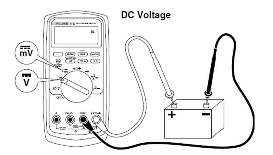
When we place the probes of a DMM on the terminals of a battery, we are measuring electromotive force or Voltage, between the positive and negative battery terminals.
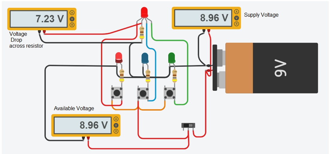
Voltage measurement applications: Technicians are concerned with the voltage in different applications:
- Source Voltage : to measure the supply voltage
- Available Voltage : to measure available voltage in the circuit.
- Voltage drop: to measure voltage drop across components.
We can measure voltage...
Between any two points in a circuit.
Between any point in a circuit and ground.
Across any component in the circuit.
Measuring AC or DC Current
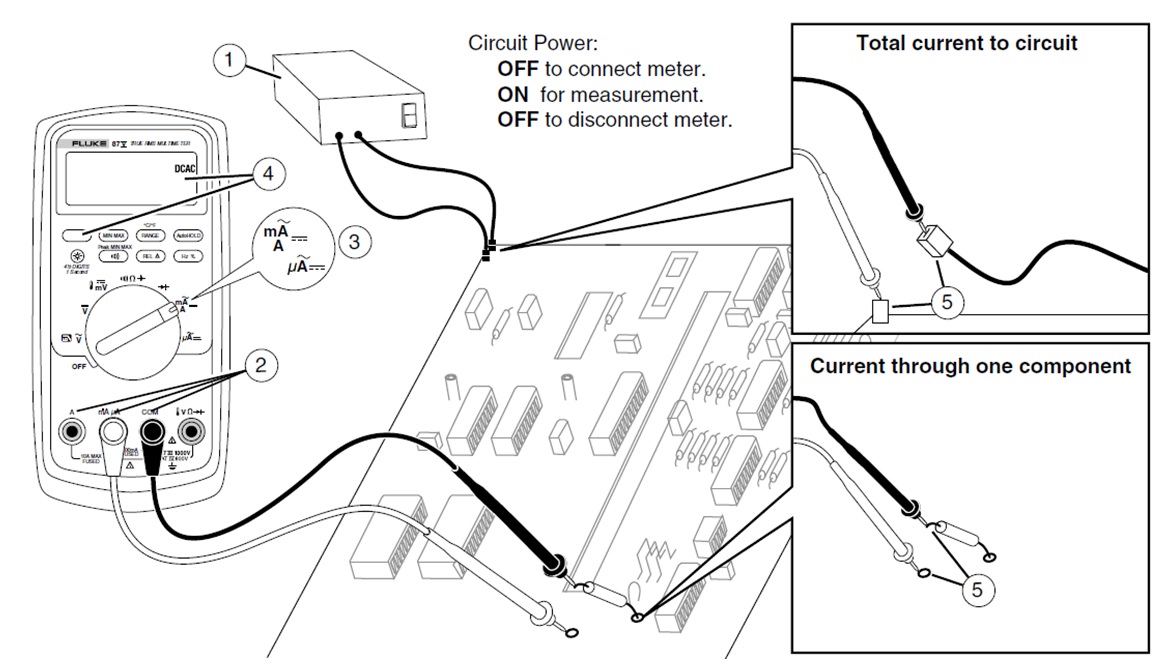
The rate at which electrons flow, i.e., current through a conductor is measured using an ammeter. To perform the measurement of current using ammeter, the circuit must be opened and then the meter is inserted in series or in-line with the circuit as shown in figure.
Caution:
Never place the probes across (in parallel with) any circuit or component when the leads are plugged into the current terminals.
Never leave the multimeter in ammeter position once the current measurement is taken.
Don't test higher currents than that of highest current measured by the multimeter in their respective ranges, i.e., mA as well as A range.
Measurement of Current with Clamp Meter
It may be difficult to open a circuit to connect in-line ammeter to measure the current. A new type of test tool that overcomes such problem is the clamp meter which comes with clamp-on current probe with multi-meter.
Measuring Resistance
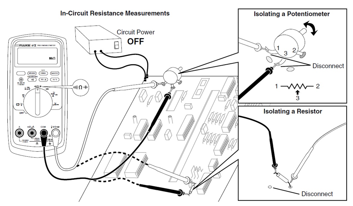
The Meter measures resistance by sending a small current through the circuit. Because this current flows through all possible paths between the probes, the resistance reading represents the total resistance of all paths between the probes.
Testing for Continuity
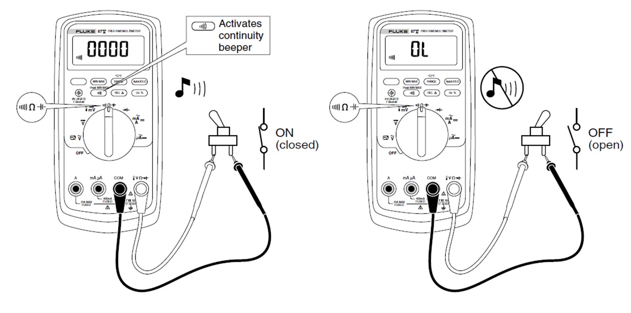
The continuity test features a beeper that sounds as long as a circuit is complete. The beeper allows you to perform quick continuity tests without having to watch the display.
Testing Diodes
To check a diode, use the diode check function on the meter and apply both forward and reverse bias. Use the diode test to check diodes, transistors, silicon controlled rectifiers (SCRs), and other semiconductor devices. This function tests a semiconductor junction by sending a current through the junction, then measuring the junction's voltage drop. A good silicon junction drops between 0.5 V and 0.8 V.
Back to contents
Soldering
Till now we have used a breadboard to build new circuits. A breadboard lets you quickly test new ideas and experiment with different components to see the result, but it isn't a permanent solution. Components can easily fall out, and there can be loose wires all over the breadboard. When you want to use a circuit for a long time without changing it, it's better to solder the circuit to a circuit board. Soldering is kind of like gluing: you melt a material called solder onto the component legs so the components stick to the circuit board.
A circuit board has holes like a breadboard, and when you solder components to it, they become connected by plates of copper. Even though soldering can create a permanent connection, it can also be reversed using a de-soldering tool
One of the most fundamental skills a technician should be able to master is the ability to solder electronics. Whether you're building a circuit or working with Arduino, knowing how to solder will come in handy. The best thing about soldering is that it's really fun to learn and easy to master.
Soldering Tools
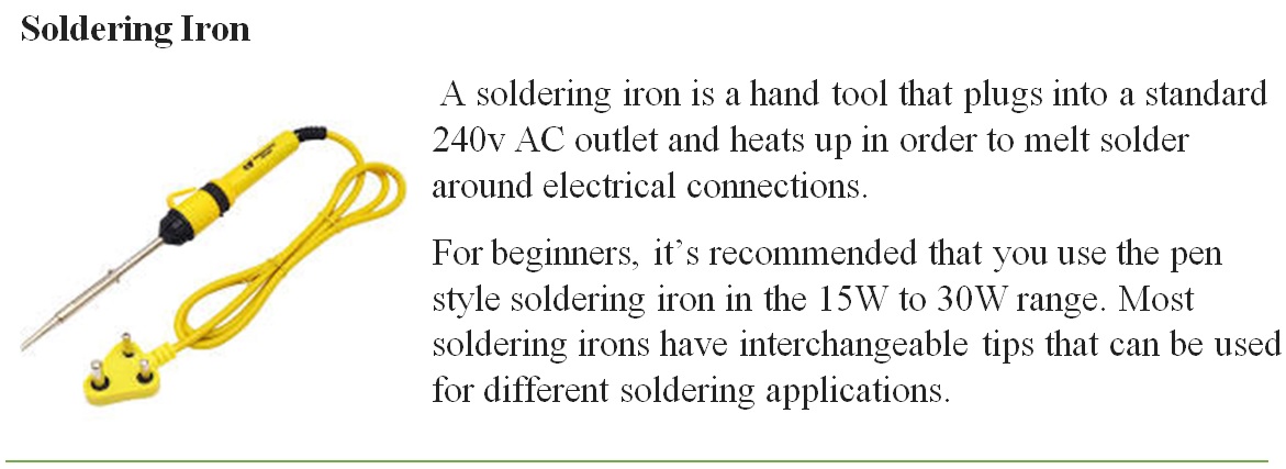
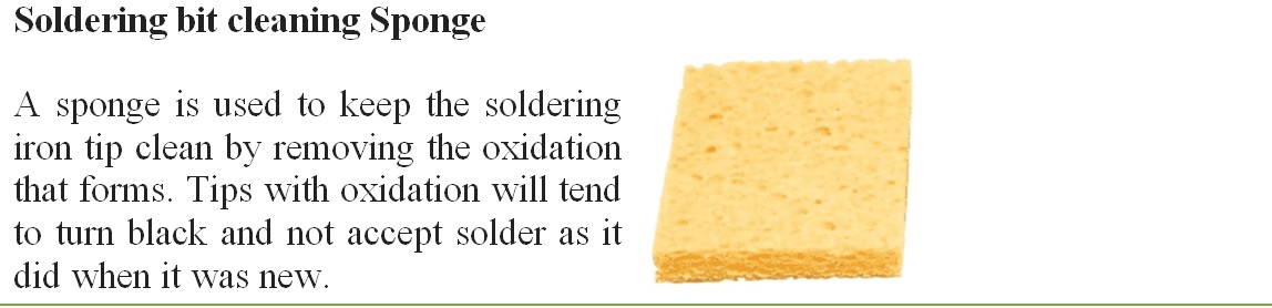
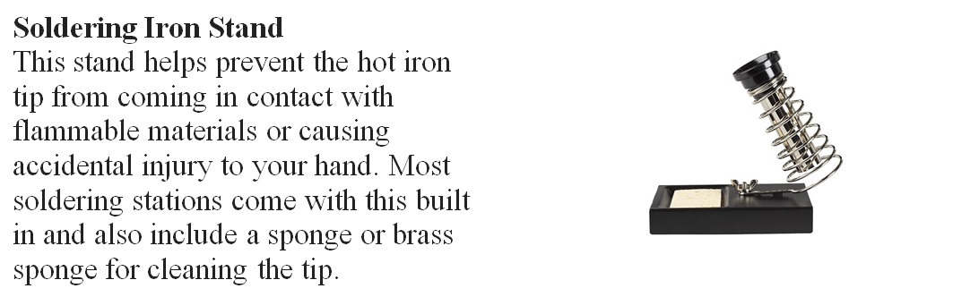
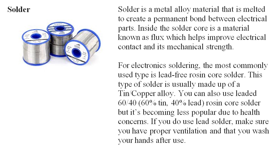
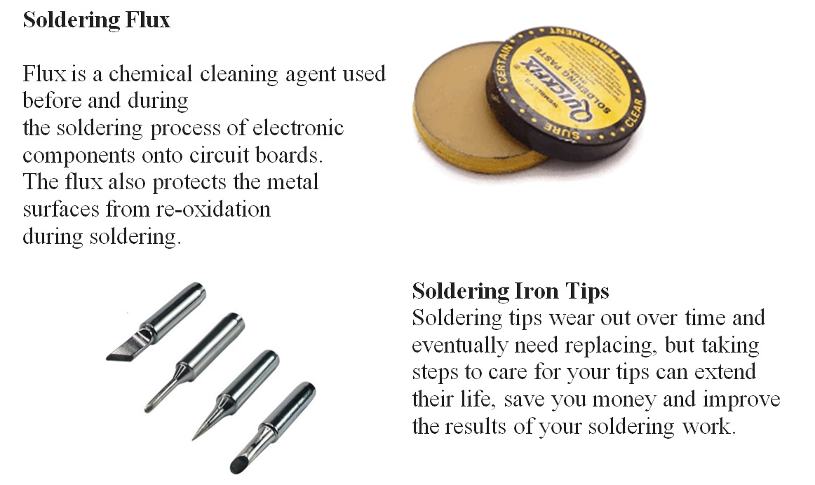
Soldering Safety Tips:
Soldering irons get extremely hot, and you can burn yourself if you touch the metal part of a soldering iron while it's plugged in. Always return the soldering iron to its stand when you're not using it; never lay it directly on a surface. Avoid touching joints (soldered connections) and components for a few seconds after you solder them, too. They can get hot enough to burn.
Here are some other important safety tips to keep in mind while soldering:
i) Keep the hot parts of the soldering iron away from the power cord.
ii) If you're soldering on a table, protect the surface with a piece of wood or some thick cardboard.
iii) Always wash your hands after handling solder.
How to Solder

1. Heat the soldering iron. After a minute or two, check whether the iron is hot enough by touching some solder to the tip of the iron. If the solder melts, your iron is ready to go.
2. Mount the component on the circuit board.
3. To heat the joint faster, add a bit of solder to the tip of the soldering iron just before you start soldering. This is called tinning. This must be done just a second or two before soldering to be effective.
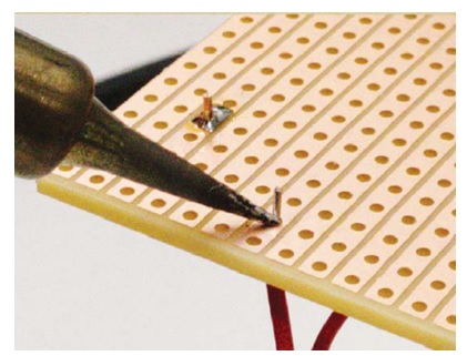
4. Place the tip of the soldering iron onto both the component leg and the copper strip. Heat the strip and leg for a couple of seconds before you move on to the next step.
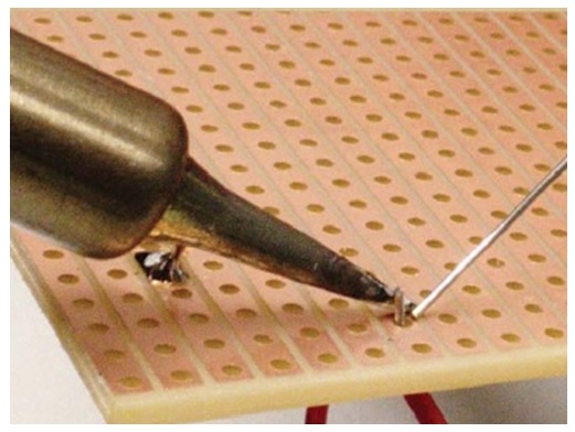
5. While keeping the soldering iron tip on the joint, touch some solder to the leg and the copper strip. As the solder melts, slowly add more until there's just enough to coat both the leg you're soldering and the copper strip you want to connect it to. When you have enough melted solder, remove the solder wire from the joint while still keeping the soldering iron tip on the joint.
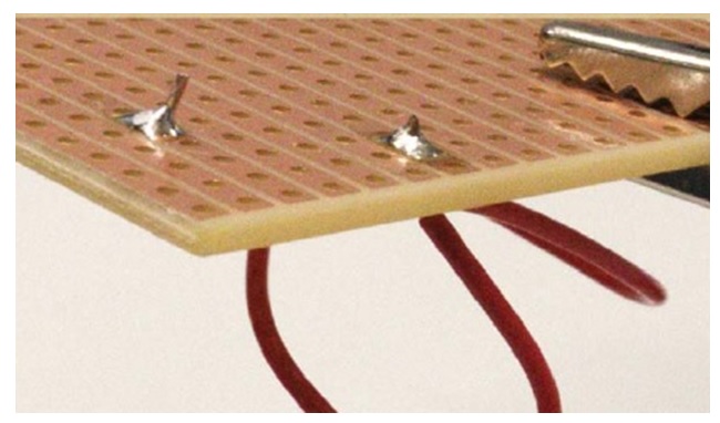
6. Remove the Soldering Iron: Finally, remove the soldering iron tip from the joint and place the iron in its stand. Always do this last. If you remove the iron while the solder wire is touching the solder joint, the solder wire may get stuck to the circuit board when the solder joint hardens.
Your solder joint should have a cone shape.
If you're done soldering, then unplug the iron so it can cool down.
Watch Out for Bad Solder Joints!
It's important to heat both the component leg and the copper strip with the iron before touching solder to either. When you heat only the component leg and not the copper strip, the solder sticks to the leg, but there's no connection between the solder and the copper strip. If only the strip is heated, the solder will stick to the strip, but not the leg. It could look like a good soldering joint from a distance, but the solder probably won't be connected to the leg.
You must also make sure the solder doesn't float over to another copper strip next to it. This will create an unintended connection between the two strips.
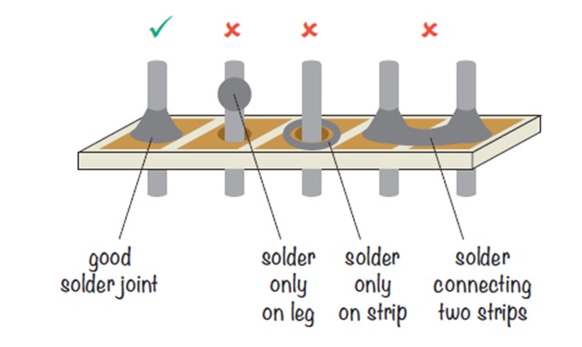
If your solder joint doesn't look right, don't worry. Just reheat the joint, the component leg, and the copper strip and add more solder to achieve the cone shape of a good solder joint.
Back to contents